Wednesday, June 24, 2020

Important Shortcut Keys System

CTRL+A. . . . . . . . . . . . . . . . . Select All

CTRL+C. . . . . . . . . . . . . . . . . Copy

CTRL+X. . . . . . . . . . . . . . . . . Cut

CTRL+V. . . . . . . . . . . . . . . . . Paste

CTRL+Z. . . . . . . . . . . . . . . . . Undo

CTRL+B. . . . . . . . . . . . . . . . . Bold

CTRL+U. . . . . . . . . . . . . . . . . Underline

CTRL+I . . . . . . . . . . . . . . . . . Italic

F1 . . . . . . . . . . . . . . . . . . . . . . Help

F2 . . . . . . . . . . . . . . . . . . . . . Rename selected object

F3 . . . . . . . . . . . . . . . . . . . . . Find all files

F4 . . . . . . . . . . . . . . . . . . . . . Opens file list drop-down in dialogs

F5 . . . . . . . . . . . . . . . . . . . . . Refresh current window

F6 . . . . . . . . . . . . . . . . . . . . . Shifts focus in Windows Explorer

F10 . . . . . . . . . . . . . . . . . . . . Activates menu bar options

ALT+TAB . . . . . . . . . . . . . . . . Cycles between open applications

ALT+F4 . . . . . . . . . . . . . . . . . Quit program, close current window

ALT+F6 . . . . . . . . . . . . . . . . . Switch between current program windows

ALT+ENTER. . . . . . . . . . . . . . Opens properties dialog

ALT+SPACE . . . . . . . . . . . . . . System menu for current window

ALT+¢ . . . . . . . . . . . . . . . . . . opens drop-down lists in dialog boxes

BACKSPACE . . . . . . . . . . . . . Switch to parent folder

CTRL+ESC . . . . . . . . . . . . . . Opens Start menu

CTRL+ALT+DEL . . . . . . . . . . Opens task manager, reboots the computer

CTRL+TAB . . . . . . . . . . . . . . Move through property tabs

CTRL+SHIFT+DRAG . . . . . . . Create shortcut (also right-click, drag)

CTRL+DRAG . . . . . . . . . . . . . Copy File

ESC . . . . . . . . . . . . . . . . . . . Cancel last function

SHIFT . . . . . . . . . . . . . . . . . . Press/hold SHIFT, insert CD-ROM to bypass auto-play

SHIFT+DRAG . . . . . . . . . . . . Move file

SHIFT+F10. . . . . . . . . . . . . . . Opens context menu (same as right-click)

SHIFT+DELETE . . . . . . . . . . . Full wipe delete (bypasses Recycle Bin)

ALT+underlined letter . . . . Opens the corresponding menu

PC Keyboard Shortcuts

Document Cursor Controls

HOME . . . . . . . . . . . . . . to beginning of line or far left of field or screen

END . . . . . . . . . . . . . . . . to end of line, or far right of field or screen

CTRL+HOME . . . . . . . . to the top

CTRL+END . . . . . . . . . . to the bottom

PAGE UP . . . . . . . . . . . . moves document or dialog box up one page

PAGE DOWN . . . . . . . . moves document or dialog down one page

ARROW KEYS . . . . . . . move focus in documents, dialogs, etc.

CTRL+ > . . . . . . . . . . . . next word

CTRL+SHIFT+ > . . . . . . selects word

Windows Explorer Tree Control

Numeric Keypad * . . . Expand all under current selection

Numeric Keypad + . . . Expands current selection

Numeric Keypad – . . . Collapses current selection

¦ . . . . . . . . . . . . . . . . . . Expand current selection or go to first child

‰ . . . . . . . . . . . . . . . . . . Collapse current selection or go to parent

Special Characters

‘ Opening single quote . . . alt 0145

’ Closing single quote . . . . alt 0146

“ Opening double quote . . . alt 0147

“ Closing double quote. . . . alt 0148

– En dash. . . . . . . . . . . . . . . alt 0150

— Em dash . . . . . . . . . . . . . . alt 0151

… Ellipsis. . . . . . . . . . . . . . . . alt 0133

• Bullet . . . . . . . . . . . . . . . . alt 0149

® Registration Mark . . . . . . . alt 0174

© Copyright . . . . . . . . . . . . . alt 0169

™ Trademark . . . . . . . . . . . . alt 0153

° Degree symbol. . . . . . . . . alt 0176

¢ Cent sign . . . . . . . . . . . . . alt 0162

1⁄4 . . . . . . . . . . . . . . . . . . . . . alt 0188

1⁄2 . . . . . . . . . . . . . . . . . . . . . alt 0189

3⁄4 . . . . . . . . . . . . . . . . . . . . . alt 0190

PC Keyboard Shortcuts

Creating unique images in a uniform world! Creating unique images in a uniform world!

é . . . . . . . . . . . . . . . alt 0233

É . . . . . . . . . . . . . . . alt 0201

ñ . . . . . . . . . . . . . . . alt 0241

÷ . . . . . . . . . . . . . . . alt 0247

File menu options in current program

Alt + E Edit options in current program

F1 Universal help (for all programs)

Ctrl + A Select all text

Ctrl + X Cut selected item

Shift + Del Cut selected item

Ctrl + C Copy selected item

Ctrl + Ins Copy selected item

Ctrl + V Paste

Shift + Ins Paste

Home Go to beginning of current line

Ctrl + Home Go to beginning of document

End Go to end of current line

Ctrl + End Go to end of document

Shift + Home Highlight from current position to beginning of line

Shift + End Highlight from current position to end of line

Ctrl + f Move one word to the left at a time

Ctrl + g Move one word to the right at a time

MICROSOFT® WINDOWS® SHORTCUT KEYS

Alt + Tab Switch between open applications

Alt +

Shift + Tab

Switch backwards between open

applications

Alt + Print

Screen

Create screen shot for current program

Ctrl + Alt + Del Reboot/Windows® task manager

Ctrl + Esc Bring up start menu

Alt + Esc Switch between applications on taskbar

F2 Rename selected icon

F3 Start find from desktop

F4 Open the drive selection when browsing

F5 Refresh contents

Alt + F4 Close current open program

Ctrl + F4 Close window in program

Ctrl + Plus

Key

Automatically adjust widths of all columns

in Windows Explorer

Alt + Enter Open properties window of selected icon

or program

Shift + F10 Simulate right-click on selected item

Shift + Del Delete programs/files permanently

Holding Shift

During Bootup

Boot safe mode or bypass system files

Holding Shift

During Bootup

When putting in an audio CD, will prevent

CD Player from playing

WINKEY SHORTCUTS

WINKEY + D Bring desktop to the top of other windows

WINKEY + M Minimize all windows

WINKEY +

SHIFT + M

Undo the minimize done by WINKEY + M

and WINKEY + D

WINKEY + E Open Microsoft Explorer

WINKEY + Tab Cycle through open programs on taskbar

WINKEY + F Display the Windows® Search/Find feature

WINKEY +

CTRL + F

Display the search for computers window

WINKEY + F1 Display the Microsoft® Windows® help

WINKEY + R Open the run window

WINKEY +

Pause /Break

Open the system properties window

WINKEY + U Open utility manager

WINKEY + L Lock the computer (Windows XP® & later)

OUTLOOK® SHORTCUT KEYS

Alt + S Send the email

Ctrl + C Copy selected text

Ctrl + X Cut selected text

Ctrl + P Open print dialog box

Ctrl + K Complete name/email typed in address bar

Ctrl + B Bold highlighted selection

Ctrl + I Italicize highlighted selection

Ctrl + U Underline highlighted selection

Ctrl + R Reply to an email

Ctrl + F Forward an email

Ctrl + N Create a new email

Ctrl + Shift + A Create a new appointment to your calendar

Ctrl + Shift + O Open the outbox

Ctrl + Shift + I Open the inbox

Ctrl + Shift + K Add a new task

Ctrl + Shift + C Create a new contact

Ctrl + Shift+ J Create a new journal entry

WORD® SHORTCUT KEYS

Ctrl + A Select all contents of the page

Ctrl + B Bold highlighted selection

Ctrl + C Copy selected text

Ctrl + X Cut selected text

Ctrl + N Open new/blank document

Ctrl + O Open options

Ctrl + P Open the print window

Ctrl + F Open find box

Ctrl + I Italicize highlighted selection

Ctrl + K Insert link

Ctrl + U Underline highlighted selection

Ctrl + V Paste

Ctrl + Y Redo the last action performed

Ctrl + Z Undo last action

Ctrl + G Find and replace options

Ctrl + H Find and replace options

Ctrl + J Justify paragraph alignment

Ctrl + L Align selected text or line to the left

Ctrl + Q Align selected paragraph to the left

Ctrl + E Align selected

Thursday, May 28, 2020

How to Install Kali Linux in USB Pen drive

1: Download Kali Linux ISO Image from the official Kali Linux website


2: Then Download Power iso, and create a bootable USB.

3: Now your are ready for the installation, Reboot your device and enter into Boot Menu.

4: choose the Bootable USB stick and you will see the Kali Linux installation option, In that choose Live system ( 1st option ).


NOTE: While entering to Live Kali Linux generally it won’t ask for username and password. In case if it asked then Type “ root “ as username and “ toor “ as password.

 5: Now open up your terminal and type the following commands one by one.


“ fdisk -l

#the above command will list out all the disk that are available in your Laptop or PC . Now note down the USB name ( mostly it will be /dev/sdb ).

fdisk /dev/sdb

#now it will ask you for command, type n and hit enter

Now press enter 4 times, and type w and hit enter.

#we have successfully created the partition.   

fdisk -l

#now check whether the partition has been created or not ( copy the name of the partition that you created now eg: /dev/sdb3 )

mkfs.ext4 -L persistence /dev/sdb3

#wait until it complete and after it completes type,

e2label /dev/sdb3 persistence

#the above command will label the partition with the name persistence.

mkdir -p /mnt/hackison (you can use any name )

mount /dev/sdb3 /mnt/hackison

echo “/ union” > /mnt/hackison/persistence.conf

umount /dev/sdb3

exit

#now reboot your laptop or Pc. and enter into your boot menu

STEP 6: In the Kali Linux Boot Menu choose the 4th option Live system ( Persistence )

STEP 7: Now Let’s check whether the persistence is working good or not. To do that just change your background or create a new folder.

STEP 8: Now reboot your device and again enter into Live System ( Persistence)

NOTE: Each and every time when you want to go to persistence mode you need to choose that option. 


Any qustions. hr610913@gmail.com


Monday, May 25, 2020

How to Configure VPN on Windows 10 Without any Softwaer

Configure VPN on Windows 10


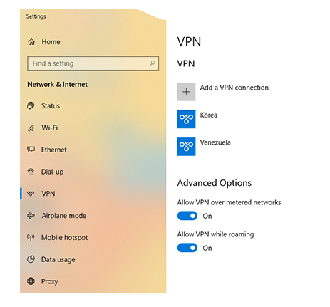
 1 - open “Network & Sharing Center, then click on VPN.
2 - select “Add a VPN connection“.                                                                                                                        

3 - Followed by filling up all the information.                                                                                                      

  • 4- At last, connect to the VPN Server from the bottom left corner by clicking on the network icon.
             

In conclusion, Now you are ready to use Free VPN on Windows without any external software.
Enjoy using your Free VPN on Windows
If you have any suggestions regarding this article please mention in the comment section down below.

Smile (“_”).


Hostname Serch Thise Web site www.vpngate/net

pless see my post On Windows 7 VPN after see WIN 10


How to Setup free VPN In pc Windows 7 Without any Softwear

             Setting up VPNGate Configuration

First  to set up a free VPN service we need to visit the  https://www.vpngate.net/ website and this will bring up the below-given website.


        Configure VPN on Windows 7  


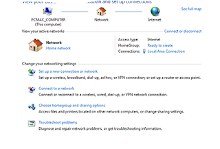
1- open Network & Sharing Center“, Click on Set up a new connection or network.

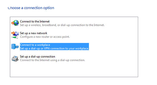
   2 -Select  “Connect to a workplace“.                                                                                                                   
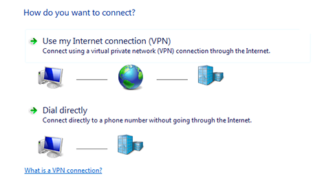
3-  choose “Use my Internet connection (VPN)                                                                                                           
4 -  type the Hostname in Internet Address and Destination Name of your choice.                                                    
Add caption
5 -
type the username as VPN and click on connect.                                                                                                
Add caption


Host Name copy on This Website .www,vpngate.net


Coming soon How to Setup VPN on Windows 10          

How to Manually add SCCP Phones to Cisco Communications Manager

Configure a SCCP phone and register the phone in Cisco Unified Communications Manager.

Activity Procedure

Complete these steps:

Before adding any SCCP phones manually into the CUCM, the MAC addresses of these Phones must be known. In this lab, for the SCCP Phones we will be using the VTGO phone. These phones will be added manually so the MAC addresses of these phones must be known/recorded.

  1. On Cisco Unified Communications Manager Administration page, from the menu select Device > Phone.
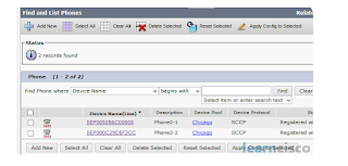
  2. On Find and list phones, click Find button to list all IP Phones have been configured on the cluster. If this is a new installation, no IP phones will be listed.
  3. Click Add New button to add new IP Phone.
  4. On Add a new phone button, select Cisco 7965 for the phone type, and click Next.
  5. Select SCCP and click Next.
  6. Add phone with the following parameter:
    - Device Name: MAC address which is used by this particular phone
    - Description: Phone2-1
    - Device Pool: Chicago
    - Owner: Anonymous
    - Phone button Template: Standard Cisco 7965 SCCP
    - Device Security Profile: Cisco 7965 - Standard SCCP Non-Secure Profile
  7. Click Save.
  8. On Phone configuration page, click Line [1] – Add a New DN link, to modify the phone number of the phone.
  9. Use the following parameter for the directory number configuration:
    - Directory number: 3001
  10. Click Save and then Apply.
  11. If you want to add more phones, you have to repeat steps 3 – 10. For example Phone 2-2 will have the following configuration:
    - Device Name: MAC address which is used by this particular phone
    - Description: Phone 2-2
    - Device Pool: Chicago
    - Owner: Anonymous
    - Phone button template: Default Cisco 7965 Template.
    - Device security profile: Standard SCCP Profile for Cisco 7965
    - Directory number: 3002
  12. Click Save and then Apply.
  13. Start the VTGO application for the required phones. (Site 2 Phone 1 & 2)
  14. Verify the TFTP Server configuration. It should point out to 10.1.1.10. You can check this by viewing the setting of the VTGO softphone.
  15. Now two IP Phones with number 3001 and 3002 have been added manually and calls can be made between these IP Phones using the 4 digit directory numbers.

Activity Verification

You have completed this task when you attain these results:

  • The IP Phones are registered with Cisco Communications Manager, they are using the Device Pool for Chicago and the button template is assigned.
  • A call between both IP Phones can be established.

IP Phone Registration

Now that the Cisco IP Phone has gone through the complete process, it is ready to register
with the call-management system (CME or CUCM). Before we discuss this final step, keep
in mind what the phone has gone through up to this point:
1. The phone has received Power over Ethernet (PoE) from the switch.
2. The phone has received VLAN information from switch via CDP.
3. The phone has received IP information from the DHCP server (including Option 150).
4. The phone has downloaded its configuration file from the TFTP server.
The Cisco IP Phone is now looking at a list of up to three call processing servers (depending
on how many you have configured) that it found in the configuration file it retrieved
from the TFTP server. The phone tries to register with the first call processing server. If
that fails, it continues down the list it received from the TFTP server until the phone
makes it through all the listed call processing servers (at which point it reboots if it finds
no servers online).
If the IP phone finds an active server in the list, it goes through the registration process using
either the Skinny Client Control Protocol (SCCP) or Session Initiation Protocol (SIP).
The protocol the phone uses depends on the firmware it is using. Today, most Cisco IP
Phones use the SCCP, which is Cisco proprietary. However, as the SIP protocol matures,
widespread support continues to grow. Because SIP is an industry standard, using it across
your network provides benefits such as vendor neutrality and inter-vendor operation.
Regardless of the protocol used, the registration process is simple: The Cisco IP Phone
contacts the call processing server and identifies itself by its MAC address. The call processing
server looks at its database and sends the operating configuration to the phone.
The operating configuration is different than the settings found in the configuration XML
file located on the TFTP server. The TFTP server configuration is “base level settings,” including
items such as device language, firmware version, call processing server IP addresses,
port numbers, and so on. The operating configuration contains items such as


directory/line numbers, ring tones, softkey layout (on-screen buttons), and so on. Although
the TFTP server configuration is sent using the TFTP protocol, the operating configuration
is sent using SIP or SCCP.
These protocols (SIP or SCCP) are then used for the vast majority of the phone functionality
following the registration. For example, as soon as a user picks up the handset of the
phone, it sends a SCCP or SIP message to the call processing server indicating an off-hook
condition. The server quickly replies with a SCCP or SIP message to play dial tone and
collect digits. As the user dials, digits are transmitted to the call processing server using
SCCP or SIP; call progress tones, such as ringback or busy, are delivered from the call processing
server to the phone using SCCP or SIP. Hopefully, you get the idea: The Cisco IP
Phone and call processing server have a dumb terminal and mainframe style of relationship,
and the “language of love” between them is SCCP or SIP.


Task 1: Configure Communications Manager System Parameters

In this Task we will prepare Cisco Unified Communications Manager for IP Phones for 2 Sites. For Chicago (Site 2) the Branch Site we will manually add Phones.

Activity Procedure

Complete these steps:

  1. From Communications Manager Administration page, go to System > Cisco Unified CM Group.
  2. On the Find and List Unified CM Group page, click Find button to list all Communications Manager Groups that have been configured on the system. If this is a new installation, there will be one Communications Manager Group called Default.
  3. Click on Communications Manager Group Default to change its configuration.
  4. On Cisco Unified Communications Manager group configuration page, if this is a new installation by default only the publisher server is selected as member for the Cisco Unified Communications Manager group default. Since there is only one Communications Manager is this topology there will not be any servers listed in the available servers list.
  5. The first item on Selected Cisco Unified Communications Managers will become the active call processing engine for this Communications Manager group.
  6. Click Save button to save any changes on the system and click Ok to restart all active devices assign with this Communications Manager group.
  7. On the Cisco Unified Communications Manager Administration page, from the menu select System > Device Pool.
  8. On Find and list Device pools page, click Find button to list all device pools configured on the system.
  9. If this is a new installation, only one device pools called default is on the list.
  10. To add new device pool, click Add new button.
  11. Create a new device pool with the following parameters:
    - Device Pool Name: Chicago
    - Cisco Unified Communications Manager group: Default
    - Date and time group: CMLocal
    - Region: default
    - SRST Reference: disable
  12. Click Save to store the new device pools configuration
  13. Repeat step 10 – 12 for another device pools with the following parameters, but do not add a new device pool. Modify the existing device pool Default with the following parameters:
    - Device Pool Name: SanJose
    - Cisco Unified Communications Manager group: Default
    - Date and time group: CMLocal
    - Region: default
    - SRST Reference: disable
  14. Confirm that the cluster have two device pools - SanJose and Chicago.

Sunday, May 24, 2020

How To Setting the Clock of a Cisco Device with NTP

The final task to prepare the network infrastructure to support a Cisco VoIP network is to
set the time. Having an accurate time on Cisco devices is important for many reasons.
Here is a quick list of just some of the reasons why you want an accurate clock on your
network devices:
■ It allows Cisco IP Phones to display the correct date and time to your users.
■ It assigns the correct date and time to voicemail tags.
■ It gives accurate times on Call Detail Records (CDR), which are used to track calls on
the network.
■ It plays an integral part in multiple security features on all Cisco devices.
■ It tags logged messages on routers and switches with accurate time information.
When Cisco devices boot, many of them default their date and time to noon on March 1,
1993. You have two options in setting the clock: manually, using the clock set command
from the privileged EXEC mode, or automatically, using the Network Time Protocol (NTP).
Devices setting the clock using NTP always have a more accurate time clock than a manually
set clock. Likewise, all the NTP devices on your network will have the exact same
time. These advantages make NTP the preferred clock-setting method. The accuracy of
the clock on your device depends on the stratum number of the NTP server. A stratum 1
time server is one that has a radio or atomic clock directly attached. The device that receives
its time from this server via NTP is considered a stratum 2 device. The device that
receives its time from this stratum 2 device via NTP is considered a stratum 3 device, and
so on. There are many publicly accessible stratum 2 and 3 (and even some stratum 1) devices on the Internet.
                  Configuring a Cisco Router to Receive Time via NTP
WAN_RTR#configure terminal
WAN_RTR(config)#ntp server 64.209.210.20
WAN_RTR(config)#clock timezone ARIZONA -7


The first command, ntp server <ip address>, configures your Cisco device to use the
specified NTP server; 64.209.210.20 is one of many publicly accessible NTP servers. If
this is the only command you enter, your clock on your device will set itself to the Universal
Time Coordinated (UTC) time zone. To accurately adjust the time zone for your device,
use the clock timezone <name> <hours> command. The previous syntax example set the
time zone for Arizona to –7 hours from UTC.
Now that we configured the router to synchronize with an NTP server, we can verify the
NTP associations and the current time and date using the commands shown 
                      Verifying NTP Configurations
RTR#show ntp associations
address ref clock st when poll reach delay offset disp
*~64.209.210.20 138.23.180.126 3 14 64 377 65.5 2.84 7.6
* master (synced), # master (unsynced), + selected, - candidate, ~ configured
WAN_RTR#show clock
11:25:48.542 CA1_DST Mon Dec 13 2010
The key information from the show ntp associations command is just to the left of the
configured NTP server address. The asterisk indicates that your Cisco device has synchronized
with this server. You can configure multiple NTP sources for redundancy, but the
Cisco device will only choose one master NTP server to use at a time.
After you configure the Cisco router to synchronize with an NTP server, you can configure
it to provide date and time information to a CUCM server, which can then provide
that date and time information to the Cisco IP Phones in your network. To allow other devices (such as a CUCM server) to pull date and time information from a Cisco router
using NTP, use the ntp master <stratum number> command from global configuration
mode. For example, entering ntp master 4 instructs the Cisco router to deliver date and
time information to requesting clients, marking it with a stratum number of 4.

How to Configuring a Router-Based DHCP Server

Using a router as a DHCP server is a somewhat common practice in smaller networks.
Once you move into larger organizations, DHCP services are typically centralized onto
server platforms. Either DHCP option is capable of sending TFTP server information to
the IP phones.
Example 3-3 shows the syntax used to configure a WAN branch router as a DHCP server.
Example 3-3 Configuring Router-Based DHCP Services
Note: This example uses a Cisco router as a DHCP server. I (Jeremy) took this approach
because using a router as a DHCP server is simple and stable. That being said, most people
use a Windows server or some other centralized device for DHCP services. Even Cisco
Unified Communications Manager includes DHCP server capabilities. In these cases, you
typically need to configure an ip helper-address <central DHCP server IP address> to
forward DHCP requests to the central DHCP server for the voice VLAN devices.
The way in which Cisco routers approach DHCP configurations is slightly different from
how many other DHCP servers do so. Most DHCP servers allow you to specify a range of
IP addresses that you would like to hand out to clients. Cisco routers take the opposite approach:
you first specify a range of addresses that you do not want to hand out to clients
(using the ip dhcp excluded-address syntax from global configuration mode). Configuring
the excluded addresses before you configure the DHCP pools ensures that the Cisco
router does not accidentally hand out IP addresses before you have a chance to exclude
them from the range. The DHCP service on the router will begin handing out IP addresses
from the first nonexcluded IP address in the network range. In Example 3-3, this is
172.16.1.10 for the voice scope and 172.16.2.10 for the data scope.
Tip: Notice a DNS server of 4.2.2.2 is assigned to both the data and voice devices. This is
a well-known, open DNS server on the Internet. This IP address works fantastically to test
connectivity and DNS services in new network deployments because it is such a simple IP
address to remember.
WAN_RTR#configure terminal
WAN_RTR(config)#ip dhcp excluded-address 172.16.1.1 172.16.1.9
WAN_RTR(config)#ip dhcp excluded-address 172.16.2.1 172.16.2.9
WAN_RTR(config)#ip dhcp pool DATA_SCOPE
WAN_RTR(dhcp-config)#network 172.16.2.0 255.255.255.0
WAN_RTR(dhcp-config)#default-router 172.16.2.1
WAN_RTR(dhcp-config)#dns-server 4.2.2.2
WAN_RTR(dhcp-config)#exit
WAN_RTR(config)#ip dhcp pool VOICE_SCOPE
WAN_RTR(dhcp-config)#network 172.16.1.0 255.255.255.0
WAN_RTR(dhcp-config)#default-router 172.16.1.1
WAN_RTR(dhcp-config)#option 150 ip 172.16.1.1
WAN_RTR(dhcp-config)#dns-server 4.2.2.2

The way in which Cisco routers approach DHCP configurations is slightly different from
how many other DHCP servers do so. Most DHCP servers allow you to specify a range of
IP addresses that you would like to hand out to clients. Cisco routers take the opposite approach:
you first specify a range of addresses that you do not want to hand out to clients
(using the ip dhcp excluded-address syntax from global configuration mode). Configuring
the excluded addresses before you configure the DHCP pools ensures that the Cisco
router does not accidentally hand out IP addresses before you have a chance to exclude
them from the range. The DHCP service on the router will begin handing out IP addresses
from the first nonexcluded IP address in the network range. In Example 3-3, this is
172.16.1.10 for the voice scope and 172.16.2.10 for the data scope.

Also notice that the VOICE_SCOPE DHCP pool includes the option 150 syntax. This creates
the custom TFTP server option to be handed out to the Cisco IP Phones along with
their IP address information. In this case, the TFTP server of the IP phones is the same as
the default gateway because we use the CME router as a call processing agent. As mentioned
in the section, “Understanding the Cisco IP Phone Boot Process,” the TFTP server
holds the configuration files for the phones. When you configure a Cisco IP Phone in
Cisco Unified Communications Manager (CUCM) or CME, an XML configuration file is
generated and stored on a TFTP server. These CML configuration files have a filename format
of SEP<IP Phone MAC Address>.cnf.xml and contain a base configuration for the IP
phone (specifying language settings, URLs, and so on). Most importantly, these XML
files contain a list of up to three CUCM server or CME IP addresses the Cisco IP Phone
uses for registration. After the IP phone receives the XML file, it attempts to register with
the first CUCM or CME server listed in the file. If it is unable to reach that server, it
moves down to the next until the list is exhausted (at which point the IP phone reboots and tries it all over again).

Design for Power Patch Panels or Inline Couplers


Powering the IP Phone with a Power Brick
Using a power brick to power a device is so simple that it warrants only brief mention.
Thus, the reason for this section is primarily to mention that most Cisco IP Phones do not
ship with power supplies. Cisco assumes most VoIP network deployments use PoE. If you
have to choose between purchasing power bricks and upgrading your switch infrastructure,
it’s wise to check the prices of the power bricks. The average Cisco IP Phone power
brick price is between $30–$40 USD. When pricing out a 48-switchport deployment, purchasing
power bricks for all the IP phones may very well be in the same price range as upgrading
the switch infrastructure.
Note: Some devices exceed the power capabilities of the 802.3af PoE standard. For
example, when you add a sidecar module to a Cisco IP Phone (typically to support more
line buttons), PoE connections can no longer support the device. These devices will need a
power brick adapter.
VLAN Concepts and Configuration
After the IP phone has received power, it must determine its VLAN assignment. Because
of security risks associated with having data and voice devices on the same network,
Cisco recommends isolating IP phones in VLANs dedicated to voice devices. To understand
how to implement this recommendation, let’s first review a few key VLAN concepts.
VLAN Review
When VLANs were introduced a number of years ago, the concept was so radical and
beneficial that it was immediately adopted into the industry. Nowadays, it is rare to find
any reasonably sized network that is not using VLANs in some way.VLANs allow you to break up switched environments into multiple broadcast domains.
Here is the basic summary of a VLAN:
A VLAN = A Broadcast Domain = An IP Subnet
There are many benefits to using VLANs in an organization, some of which include the
following:
■ Increased performance: By reducing the size of the broadcast domain, network
devices run more efficiently.
■ Improved manageability: The division of the network into logical groups of users,
applications, or servers allows you to understand and manage the network better.
■ Physical topology independence: VLANs allow you to group users regardless of
their physical location in the campus network. If departments grow or relocate to a
new area of the network, you can simply change the VLAN on their new ports without
making any physical network changes.
■ Increased security: A VLAN boundary marks the end of a logical subnet. To reach
other subnets (VLANs), you must pass through a routed (Layer 3) device. Any time
you send traffic through a router, you have the opportunity to add filtering options
(such as access lists) and other security measures.
VLAN Trunking/Tagging
VLANs are able to transcend individual switches, as shown in Figure 3-4.
If a member of VLAN_GRAY sends a broadcast message, it goes to all VLAN_GRAY
ports on both switches. The same holds true for VLAN_WHITE. To accommodate this,
the connection between the switches must carry traffic for multiple VLANs. This type of
port is known as a trunk port.
Trunk ports are often called tagged ports because the switches send frames between each
other with a VLAN “tag” in place. Figure 3-5 illustrates the following process:
1. HostA (in VLAN_GRAY) wants to send data to HostD (also in VLAN_GRAY).
HostA transmits the data to SwitchA.
2. SwitchA receives the data and realizes that HostD is available through the FastEthernet
0/24 port (because HostD’s MAC address has been learned on this port). Because
FastEthernet 0/24 is configured as a trunk port, SwitchA puts the VLAN_GRAY tag
in the IP header and sends the frame to SwitchB.
3. SwitchB processes the VLAN_GRAY tag because the FastEthernet 0/24 port is configured
as a trunk. Before sending the frame to HostD, the VLAN_GRAY tag is removed
from the header.
4. The tagless frame is sent to HostD.
58 CCNA Voice 640-461 Official Cert Guide
Using this process, the PC never knows what VLAN it belongs to. The VLAN tag is applied
when the incoming frame crosses a trunk port. The VLAN tag is removed when exiting
the port to the destination PC. Always keep in mind that VLANs are a switching
concept; the PCs never participate in the VLAN tagging process.
VLANs are not a Cisco-only technology. Just about all managed switch vendors support
VLANs. In order for VLANs to operate in a mixed-vendor environment, a common trunking
or “tagging” language must exist between them. This language is known as 802.1Q. All
vendors design their switches to recognize and understand the 802.1Q tag, which is what
allows us to trunk between switches in any environment.
Understanding Voice VLANs
It is a common and recommended practice to separate voice and data traffic by using
VLANs. There are already easy-to-use applications available, such as Wireshark and Voice
Over Misconfigured Internet Telephones (VOMIT), that allow intruders to capture voice
conversations on the network and convert them into WAV data files. Separating voice and
data traffic using VLANs provides a solid security boundary, preventing data applications
from reaching the voice traffic. It also gives you a simpler method to deploy QoS, prioritizing
the voice traffic over the data.
One initial difficulty you can encounter when separating voice and data traffic is the fact
that PCs are often connected to the network using the Ethernet port on the back of a
Cisco IP Phone. Because you can assign a switchport to only a single VLAN, it initially
seems impossible to separate voice and data traffic. That is, until you see that Cisco IP
Phones support 802.1Q tagging.
The switch built into Cisco IP Phones has much of the same hardware that exists inside of
a full Cisco switch. The incoming switchport is able to receive and send 802.1Q tagged
packets. This gives you the capability to establish a type of trunk connection between the Cisco switch and IP phone, as shown in Figure
Sure enough, VLANs 10 (VOICE) and 50 (DATA) now appear as valid VLANs on the
switch. Now that the VLANs exist, you can assign the ports attaching to Cisco IP Phones
(with PCs connected to the IP Phone) to the VLANs, as shown in Example 3-2.
Example 3-2 Assigning Voice and Data VLANs
Note: When connecting Cisco IP Phones to a switch, you should also enable portfast
(using spanning-tree portfast, as shown in Example 3-2), because the IP phones boot
quickly and request a DHCP assigned address before a typical port with spanning-tree
enabled would go active. Also, keep in mind that port Fa0/1 does not appear in the
Example 3-2 output because it is configured as a trunk port (ports 2–24 are not considered
trunks by Cisco IOS).
The ports are now configured to support a voice VLAN of 10 and a data VLAN of 50.
This syntax is a newer form of configuration for IP Phone connections. In the “old days,”
you would configure the interface as a trunk port because the switch was establishing a
trunking relationship between it and the IP phone. This was less secure because a hacker
could remove the IP phone from the switchport and attach their own device (another managed
Switch#configure terminal
Switch(config)#interface range fa0/2 - 24
Switch(config-if-range)#switchport mode access
Switch(config-if-range)#spanning-tree portfast
Switch(config-if-range)#switchport access vlan 50
Switch(config-if-range)#switchport voice vlan 10
Switch(config-if-range)#end
Switch#show vlan brief
VLAN Name Status Ports
—— ———————————————— ————- ———————————————-
1 default active Gi0/1, Gi0/2
10 VOICE active Fa0/2, Fa0/3, Fa0/4, Fa0/5
Fa0/6, Fa0/7, Fa0/8, Fa0/9
Fa0/10, Fa0/11, Fa0/12, Fa0/13
Fa0/14, Fa0/15, Fa0/16, Fa0/17
Fa0/18, Fa0/19, Fa0/20, Fa0/21
Fa0/22, Fa0/23, Fa0/24
50 DATA active Fa0/2, Fa0/3, Fa0/4, Fa0/5
Fa0/6, Fa0/7, Fa0/8, Fa0/9
Fa0/10, Fa0/11, Fa0/12, Fa0/13
Fa0/14, Fa0/15, Fa0/16, Fa0/17
Fa0/18, Fa0/19, Fa0/20, Fa0/21
Fa0/22, Fa0/23, Fa0/24
1002 fddi-default act/unsup
1003 token-ring-default act/unsup
1004 fddinet-default act/unsup
1005 trnet-default act/unsup