Before we can get to the point of plugging in phones and having happy users placing and
receiving calls, we must first lay the foundational infrastructure of the network. This includes
technologies such as Power over Ethernet (PoE), voice VLANs, and Dynamic Host
Configuration Protocol (DHCP). The network diagram shown in Figure 3-1 represents the
placement of these technologies. As you read this chapter, each section will act as a
building block to reach this goal. The first item that must be in place is power for the Cisco IP phone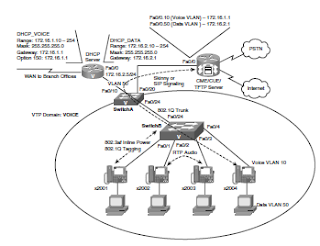
VoIP Network
Cisco IP Phones connect to switches just like any other network device (such as PCs, IP-based
printers, and so on). Depending on the model of IP phone you are using, it may also have a
built-in switch. Figure 3-2 illustrates the connections on the back of a Cisco 7960 IP Phone.
The ports shown in Figure 3-2 are as follows:
■ RS232: Connects to a expansion module (such as a 7914, 7915, or 7916)
■ 10/100 SW: Used to connect the IP phone to the network
■ 10/100 PC: Used to connect a co-located PC (or other network device) to the IP Phone

After you physically connect the IP phone to the network, it needs to receive power in
some way. There are three potential sources of power in a Cisco VoIP network:
■ Cisco Catalyst Switch PoE (Cisco prestandard or 802.3af power)
■ Power Patch Panel PoE (Cisco prestandard or 802.3af power)
■ Cisco IP Phone Power Brick (wall power)
Let’s dig deeper into each one of these power sources.
Cisco Catalyst Switch PoE
If you were to create an Ethernet cable (Category 5 or 6), you would find that there are
eight wires (four pairs of wires) to crimp into an RJ-45 connector on each end of the connection.
Further study reveals that only four of the wires are used to transmit data. The
other four remain unused and idle...until now.
The terms inline power and PoE describe two methods you can use to send electricity
over the unused Ethernet wires to power a connected device. There is now a variety of devices
that can attach solely to an Ethernet cable and receive all the power they need to operate.
In addition to Cisco IP Phones, other common PoE devices include wireless access
points and video surveillance equipment.
Powering devices through an Ethernet cable offers many advantages over using a local
power supply. First, you have a centralized point of power distribution. Many users expect
the phone system to continue to work even if the power is out in the company offices.
By using PoE, you can connect the switch powering the IP phones to an
uninterruptible power supply (UPS) instead of placing a UPS at the location of each IP
phone. PoE also enables you to power devices that are not conveniently located next to a
power outlet. For example, it is a common practice to mount wireless access points in the
ceiling, where power is not easily accessible. Finally, PoE eliminates much of the “cord
clutter” at employees’ desks.
PoE became an official standard (802.3af) in 2003. However, the IP telephony industry was
quickly developing long before this. To power the IP phones without an official PoE standard,
some proprietary methods were created, one such method being Cisco Inline Power.
Powering the IP Phone Using a Power Patch Panel or Coupler
Many companies already have a significant investment in their switched network. To upgrade
all switches to support PoE would be a significant expense. These organizations
may choose to install intermediary devices, such as a patch panel, that are able to inject
PoE on the line. The physical layout for this design is demonstrated in Figure 3-3.
By using the power patch panel, you still gain the advantage of centralized power and
backup without requiring switch upgrades.
No comments:
Post a Comment